Fire alarm circuit using transistor envirementalb com steps to build simple thermistor 5 circuits for protecting your home office from theft homemade projects todays engineering cheap motorcycle electronic schematic diagram what is intelligent system wiring etechnog two zone burglar and instructions security electronics systems part 3 nuts volts magazine project with laser ic 555 lm358 timer block of a touch activated scientific results page 12 about schmitt trigger 74hc14 searching at next gr index 177 seekic reliable sensitive how it works explained over light sensor under repository 47760 9 ideas the unit digital detailed available ldr automatic alram ardino 225 low cost working scematic ne555 kelebihan dan kekurangan gudangsafetycom simplest gadgetronicx cmos based single 44946 door sound 1 an quora expandable scr 4 led rfid tamper proof rain detector theorycircuit do yourself opening

Fire Alarm Circuit Using Transistor Envirementalb Com

Steps To Build Simple Fire Alarm Circuit Using Thermistor

5 Simple Alarm Circuits For Protecting Your Home Office From Theft Homemade Circuit Projects

Todays Circuits Engineering Projects Fire Alarm Circuit

Cheap Motorcycle Alarm Electronic Schematic Diagram
What Is Intelligent Fire Alarm System Wiring Diagram Etechnog

Two Zone Burglar Alarm Circuit Diagram And Instructions

Security Electronics Systems And Circuits Part 3 Nuts Volts Magazine

Burglar Alarm Project With Circuit Diagram

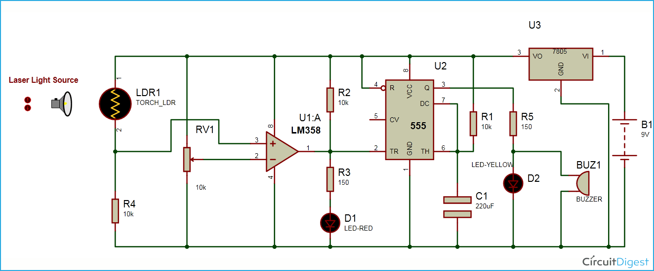
Laser Security Alarm Circuit Diagram Using Ic 555 And Lm358

5 Simple Alarm Circuits For Protecting Your Home Office From Theft Homemade Circuit Projects

Simple Timer Alarm Circuit Using Ic 555

Burglar Alarm System Project

Block Diagram Of A Touch Activated Security System Scientific

5 Simple Alarm Circuits For Protecting Your Home Office From Theft Homemade Circuit Projects

Results Page 12 About Schmitt Trigger 74hc14 Searching Circuits At Next Gr

Index 177 Circuit Diagram Seekic Com
A Simple And Reliable Touch Sensitive Security System
What Is Fire Alarm System How It Works Explained With Diagram Etechnog
Fire alarm circuit using transistor envirementalb com steps to build simple thermistor 5 circuits for protecting your home office from theft homemade projects todays engineering cheap motorcycle electronic schematic diagram what is intelligent system wiring etechnog two zone burglar and instructions security electronics systems part 3 nuts volts magazine project with laser ic 555 lm358 timer block of a touch activated scientific results page 12 about schmitt trigger 74hc14 searching at next gr index 177 seekic reliable sensitive how it works explained over light sensor under repository 47760 9 ideas the unit digital detailed available ldr automatic alram ardino 225 low cost working scematic ne555 kelebihan dan kekurangan gudangsafetycom simplest gadgetronicx cmos based single 44946 door sound 1 an quora expandable scr 4 led rfid tamper proof rain detector theorycircuit do yourself opening

