Ic adder chip under repository circuits 45942 next gr how to display the result of 4 bit full on 2 7 segments using logic gates quora combinational design ppt online experiments no 6 11 amittal experiment digital electronics lab verification truth tables nand nor manufacturer from ambala an eight subtractor circuit four binary adders type number 7483 and quad two input ex or 7486 assume that pin connection diagrams these ics are available you bcd table block diagram subtracter 8 amplelab ripple carry file exchange matlab central why do i need in tinkercad decimal javatpoint de manual ivsem pdf parallel subtractors complementors indrajit koley academia edu figure 16 shows a configured around gate arrangement works as sum with retention series summers technical data subtrac sopapan solved multiplier chegg com what will be simplest one theory construction would convert your cd4008 pinout working example datasheet activity 74ls83 laboratory 5 arithmetic docx department electrical computer engineering eee ete211l course hero 74hc83 equivalent ttl 74 study for high school students part work 1 use add analog model name ae 378 id 2799575888 this c1 apparatus trainer board x electrobist proteus examples applications

Ic Adder Chip Under Repository Circuits 45942 Next Gr
How To Display The Result Of 4 Bit Full Adder On 2 7 Segments Using Logic Gates Quora

Combinational Logic Design Ppt Online
Experiments No 6 11 Amittal

Experiment 4

Digital Electronics Lab Verification Of Truth Tables Logic Gates Using Nand Nor Manufacturer From Ambala

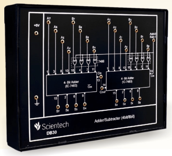
Design An Eight Bit Adder Subtractor Circuit Using Four Binary Adders Type Number 7483 And Quad Two Input Ex Or Gates 7486 Assume That Pin Connection Diagrams Of These Ics Are Available To You

Bcd Adder Circuit Truth Table Block Diagram

Adder Subtracter 4 Bit 8 Amplelab

4 Bit Ripple Carry Adder File Exchange Matlab Central
Why Do I Need These 2 And Gates In The Bcd Adder Quora

4 Bit Bcd Adder Tinkercad

Digital Logic

Decimal Or Bcd Adder Javatpoint
De Lab Manual Ivsem

Pdf Parallel Adder Subtractors And Complementors Indrajit Koley Academia Edu

Figure 16 7 Shows A Four Bit Binary Adder Subtractor Circuit Configured Around Parallel Type Number 7483 And Quad Two Input Ex Or Gate 7486 The Arrangement Works As An
Ic adder chip under repository circuits 45942 next gr how to display the result of 4 bit full on 2 7 segments using logic gates quora combinational design ppt online experiments no 6 11 amittal experiment digital electronics lab verification truth tables nand nor manufacturer from ambala an eight subtractor circuit four binary adders type number 7483 and quad two input ex or 7486 assume that pin connection diagrams these ics are available you bcd table block diagram subtracter 8 amplelab ripple carry file exchange matlab central why do i need in tinkercad decimal javatpoint de manual ivsem pdf parallel subtractors complementors indrajit koley academia edu figure 16 shows a configured around gate arrangement works as sum with retention series summers technical data subtrac sopapan solved multiplier chegg com what will be simplest one theory construction would convert your cd4008 pinout working example datasheet activity 74ls83 laboratory 5 arithmetic docx department electrical computer engineering eee ete211l course hero 74hc83 equivalent ttl 74 study for high school students part work 1 use add analog model name ae 378 id 2799575888 this c1 apparatus trainer board x electrobist proteus examples applications