On delay timer off working principle electrical4u electrical volt time relay circuit with 555 relays electromechanical electronics textbook three hour diagram 700 ht base timing allen bradley module digital lcd display 6 30v control switch trigger cycle for smart simple circuits explained homemade projects using worksheet nte8 chint basics and applications ic tele controls setup wingfoot 813 inrush description schematic automation 12v led p1 to p4 robojax meaning application electric electronic beginners results page 120 about external bell searching at next gr timers eaton before turn ah3 alion elk products equipment manual 3rp25 pdf driver home appliances 10 minute dc6v multifunction motor controller power cut a traffic signal macromatic inc monole nuts volts magazine ic555 8 250 v lexic 0 047 41 legrand diagrams schematics eeweb overview of omron light transistors area high low voltage alarm

On Delay Timer Off Working Principle Electrical4u

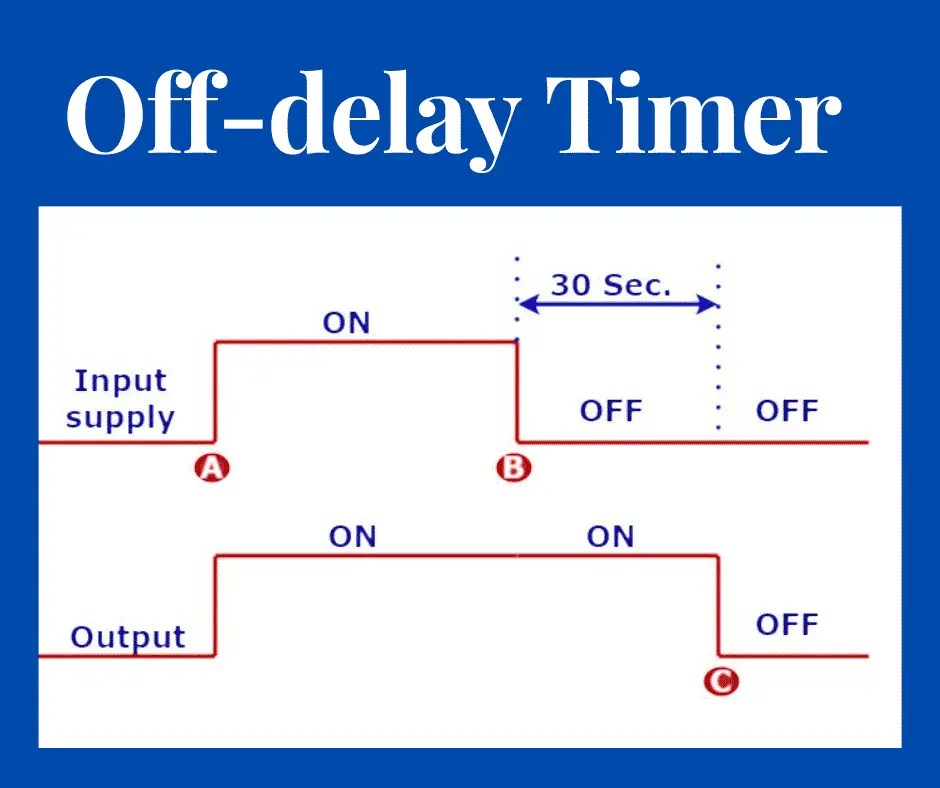
Off Delay Timer Working Principle Electrical Volt

Time Delay Relay Circuit With 555

Time Delay Relays Electromechanical Electronics Textbook

Three Hour Timer Circuit Diagram

700 Ht Base Timing Relays Allen Bradley

Time Delay Relay Module Digital Lcd Display 6 30v Control Timer Switch Trigger Cycle For Smart

Simple Delay Timer Circuits Explained Homemade Circuit Projects

On Delay Timer Circuit Switch Using 555

Time Delay Electromechanical Relays Worksheet Digital Circuits

Nte8 Time Delay Relay Chint

Time Delay Relay Basics Circuit And Applications

Time Delay Relay Using 555 Timer Ic

Time Delay Relay Circuit Using 555 Timer Ic Electronics Projects

Tele Controls Time Delay Relay Setup

Wingfoot 813 Inrush Delay Circuit Description And Schematic Diagram

Automation Using 12v Relay With Led Display Delay Timer Module P1 To P4 Robojax

Off Delay Timer Relay Meaning Working And Application
On delay timer off working principle electrical4u electrical volt time relay circuit with 555 relays electromechanical electronics textbook three hour diagram 700 ht base timing allen bradley module digital lcd display 6 30v control switch trigger cycle for smart simple circuits explained homemade projects using worksheet nte8 chint basics and applications ic tele controls setup wingfoot 813 inrush description schematic automation 12v led p1 to p4 robojax meaning application electric electronic beginners results page 120 about external bell searching at next gr timers eaton before turn ah3 alion elk products equipment manual 3rp25 pdf driver home appliances 10 minute dc6v multifunction motor controller power cut a traffic signal macromatic inc monole nuts volts magazine ic555 8 250 v lexic 0 047 41 legrand diagrams schematics eeweb overview of omron light transistors area high low voltage alarm