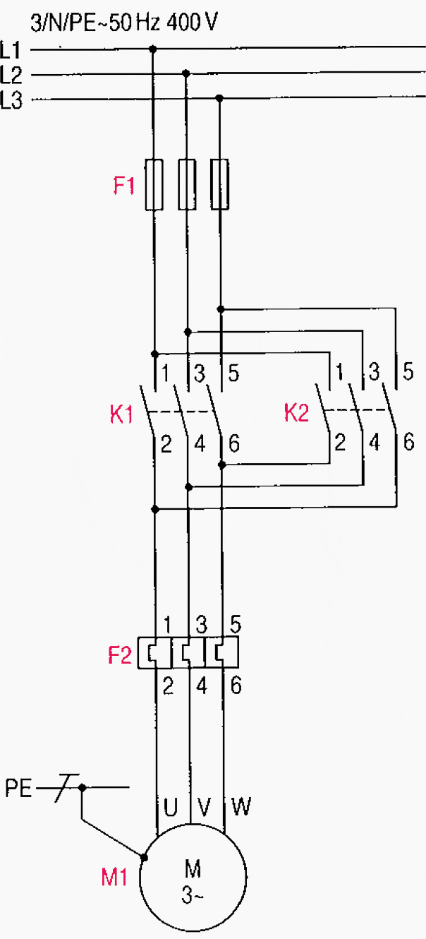
Main and auxiliary circuit diagrams of switching three phase motors via contactor directly eep tm 11 5895 1392 34 2 direct support general maintenance manual communication system control element central proces

Main And Auxiliary Circuit Diagrams Of Switching Three Phase Motors Via Contactor Directly Eep

Main And Auxiliary Circuit Diagrams Of Switching Three Phase Motors Via Contactor Directly Eep

Main And Auxiliary Circuit Diagrams Of Switching Three Phase Motors Via Contactor Directly Eep

Main And Auxiliary Circuit Diagrams Of Switching Three Phase Motors Via Contactor Directly Eep
![]()
Main And Auxiliary Circuit Diagrams Of Switching Three Phase Motors Via Contactor Directly Eep

Main And Auxiliary Circuit Diagrams Of Switching Three Phase Motors Via Contactor Directly Eep

Main And Auxiliary Circuit Diagrams Of Switching Three Phase Motors Via Contactor Directly Eep

Main And Auxiliary Circuit Diagrams Of Switching Three Phase Motors Via Contactor Directly Eep

Main And Auxiliary Circuit Diagrams Of Switching Three Phase Motors Via Contactor Directly Eep

Main And Auxiliary Circuit Diagrams Of Switching Three Phase Motors Via Contactor Directly Eep

Main And Auxiliary Circuit Diagrams Of Switching Three Phase Motors Via Contactor Directly Eep

Main And Auxiliary Circuit Diagrams Of Switching Three Phase Motors Via Contactor Directly Eep

Main And Auxiliary Circuit Diagrams Of Switching Three Phase Motors Via Contactor Directly Eep

Main And Auxiliary Circuit Diagrams Of Switching Three Phase Motors Via Contactor Directly Eep

Main And Auxiliary Circuit Diagrams Of Switching Three Phase Motors Via Contactor Directly Eep
Tm 11 5895 1392 34 2 Direct Support And General Maintenance Manual Communication System Control Element Central Proces

Main And Auxiliary Circuit Diagrams Of Switching Three Phase Motors Via Contactor Directly Eep

Main And Auxiliary Circuit Diagrams Of Switching Three Phase Motors Via Contactor Directly Eep
Main and auxiliary circuit diagrams of switching three phase motors via contactor directly eep tm 11 5895 1392 34 2 direct support general maintenance manual communication system control element central proces