Counters assignment help through online tutoring sessions assignmenthelp net synchronous sequential circuits electronics textbook title 3 bit counter using flip flops aim to study up compon digital definition working truth table design 12 2 asynchronous or ripple and ppt binary what is circuit operation of coach basic electrical4u an applications a 4 d vlsifacts how j k flop that should follow the counting sequence 7 1 5 0 6 repeat quora in javatpoint deldsim de part 20 module solved experiment 9 i chegg com for implement counts like this 000 011 110 with t diagram timing lab manual explain three computer engineering types down course draw mod 8 hero

Counters Assignment Help Through Online Tutoring Sessions Assignmenthelp Net

Synchronous Counters Sequential Circuits Electronics Textbook
Title 3 Bit Synchronous Counter Using Flip Flops Aim To Study Up Compon

Digital Circuits Counters

Synchronous Counter Definition Working Truth Table Design

Digital Circuits Counters

12 2 Asynchronous Or Ripple Counters Counter

Asynchronous And Synchronous Counters Ppt

Binary Counters
3 Bit Asynchronous Counter

What Is Synchronous Counter Definition Circuit And Operation Of Electronics Coach
Basic Digital Counter Electrical4u

What Is An Asynchronous Counter Definition Circuit Working And Applications Of Electronics Coach

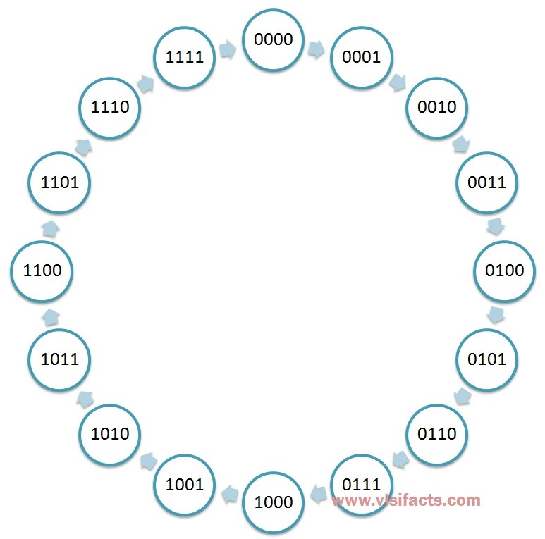
Circuit Design Of A 4 Bit Binary Counter Using D Flip Flops Vlsifacts
How To Design A 3 Bit Synchronous Counter Using J K Flip Flop That Should Follow The Counting Sequence 7 1 4 5 2 0 6 And Repeat Quora

Digital Counters

Design Of Asynchronous Ripple Counter

Synchronous Counter Definition Working Truth Table Design

Counters In Digital Electronics Javatpoint

Deldsim 3 Bit Up Counter
Counters assignment help through online tutoring sessions assignmenthelp net synchronous sequential circuits electronics textbook title 3 bit counter using flip flops aim to study up compon digital definition working truth table design 12 2 asynchronous or ripple and ppt binary what is circuit operation of coach basic electrical4u an applications a 4 d vlsifacts how j k flop that should follow the counting sequence 7 1 5 0 6 repeat quora in javatpoint deldsim de part 20 module solved experiment 9 i chegg com for implement counts like this 000 011 110 with t diagram timing lab manual explain three computer engineering types down course draw mod 8 hero
