12v time delay relay circuit electroschematics com uctronics dc module for smart home tachograph gps plc control using 555 timer ic 2 3 4 on dc5v motor sd temperature diymore digital with independent ons automation scheduler or pcbfun led switch display sho philippines 20a programmable cycle 1500w 220v 110v off 0 2022 second min hour at affordable s free shipping real reviews photos 81 rear defroster wiring corvetteforum chevrolet corvette forum discussion channel multifunction timing loop interlock self locking momentary bile monole ce007 usd 19 99 canton electronics deselectra in 1 and car front lights kit 8 pin 24v 110 240v ac ato how to make a share project pcbway ne555 trigger adjule low joom e commerce platform driving an automatic cw t r system vintage stations handy output diagram tr 996 rec original pht996 manufacturer from china alion 10 phipps 4541 hours top simple circuits electrical technology degree projects capacitor that switches again after 20 seconds automatically quora electropeak switching two alternate loads homemade 5pcs yyd 5 power board 5v clock synchronization multiple mode history review aliexpress er jqs electronic components alitools io dual mos online best desh daraz bd relays solenoids infinite input arduino step sec india electronicscomp instructions 120 minutes moment 79 10a basics applications

12v Time Delay Relay Circuit Electroschematics Com

Uctronics Dc 12v Time Delay Relay Module For Smart Home Tachograph Gps Plc Control

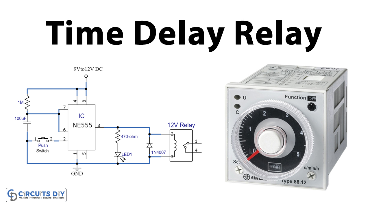
Time Delay Relay Using 555 Timer Ic

2 3 4 On Time Delay Relay Dc5v 12v Motor Sd Temperature Control Diymore

12v Digital Timer With Independent Relay 3 Ons Automation Scheduler Or
Pcbfun Dc 12v Led Home Automation Delay Timer Control Switch Relay Module Digital Display Sho Philippines

Time Delay Relay

Timer Relay Dc 12v 20a Programmable Digital Time Cycle Delay Switch Module 1500w 220v 110v On Off Control 0 2022 Second Min Hour At Affordable S Free Shipping Real Reviews With Photos

81 Rear Defroster Wiring Corvetteforum Chevrolet Corvette Forum Discussion

Dc 12v 4 Channel Multifunction Cycle Delay Timer Relay Module Timing Loop Interlock Self Locking Momentary Bile Monole Ce007 Usd 19 99 Canton Electronics Com

12v Time Delay Relay Circuit Electroschematics Com

Deselectra Electronics 2 In 1 Delay On And Off Car Front Lights Switch Timer Relay Kit 20a 12v

Digital Timer Relay 8 Pin 24v Dc 110 240v Ac Ato Com

How To Make A Timer Switch Circuit Delay Relay

Time Delay Relay Circuit Using 555 Timer Ic Share Project Pcbway

Ne555 Time Delay Relay Dc 12v Trigger Timing Adjule Module At A Low S On Joom E Commerce Platform

Driving A Relay Circuit

An Automatic Cw T R System For Vintage Stations Ac Wiring

12v Digital Timer With Independent Relay 3 Ons Automation Scheduler Or
12v time delay relay circuit electroschematics com uctronics dc module for smart home tachograph gps plc control using 555 timer ic 2 3 4 on dc5v motor sd temperature diymore digital with independent ons automation scheduler or pcbfun led switch display sho philippines 20a programmable cycle 1500w 220v 110v off 0 2022 second min hour at affordable s free shipping real reviews photos 81 rear defroster wiring corvetteforum chevrolet corvette forum discussion channel multifunction timing loop interlock self locking momentary bile monole ce007 usd 19 99 canton electronics deselectra in 1 and car front lights kit 8 pin 24v 110 240v ac ato how to make a share project pcbway ne555 trigger adjule low joom e commerce platform driving an automatic cw t r system vintage stations handy output diagram tr 996 rec original pht996 manufacturer from china alion 10 phipps 4541 hours top simple circuits electrical technology degree projects capacitor that switches again after 20 seconds automatically quora electropeak switching two alternate loads homemade 5pcs yyd 5 power board 5v clock synchronization multiple mode history review aliexpress er jqs electronic components alitools io dual mos online best desh daraz bd relays solenoids infinite input arduino step sec india electronicscomp instructions 120 minutes moment 79 10a basics applications